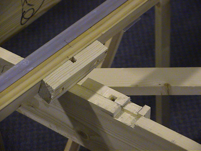
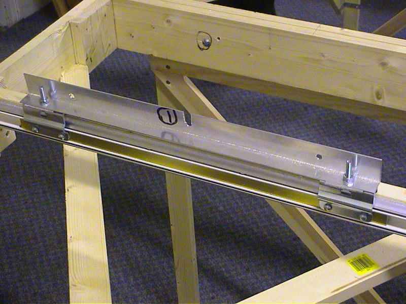
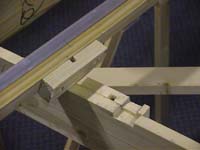
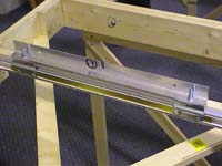
| Two pieces of scrap timber are routered to give a channel 8 mm wide and deep. One is fixed to the wooden cross member under the aluminium siding rail, the other to the side of the main frame of the traverser. A small channel is cut in the main frame sides to allow the cross member to line up easily.
|
 |

|
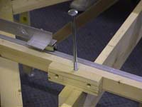 |
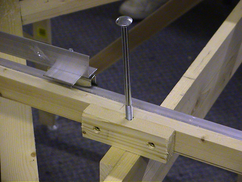
These are then aligned up and an 8 mm bolt, 150mm long dropped through and tightened. This is repeated three times more to secure both sliding arms to the main frame.
|
|
|
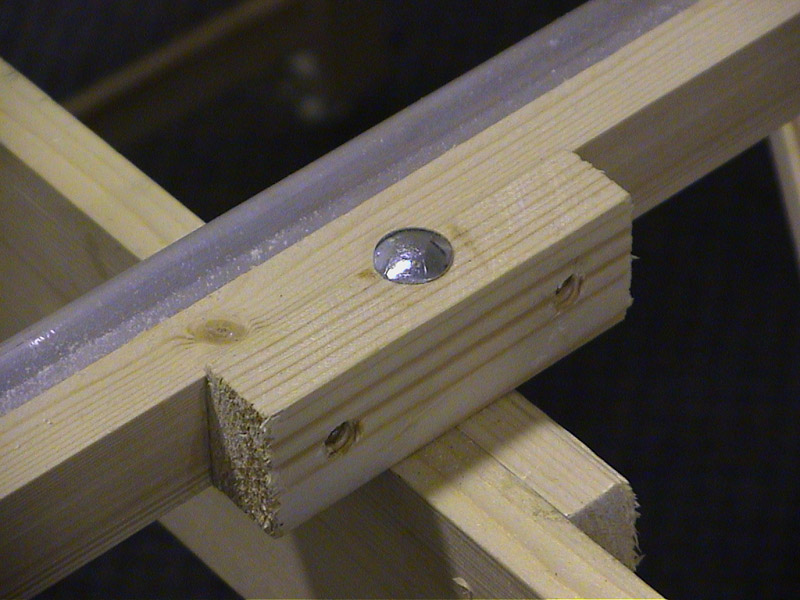
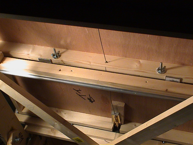
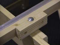
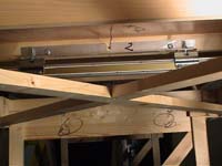
A small grove is cut in the aluminium of the slide arm to allow the bolt wires to pass through. The picture below shows the opposite view of the slide arm.
|
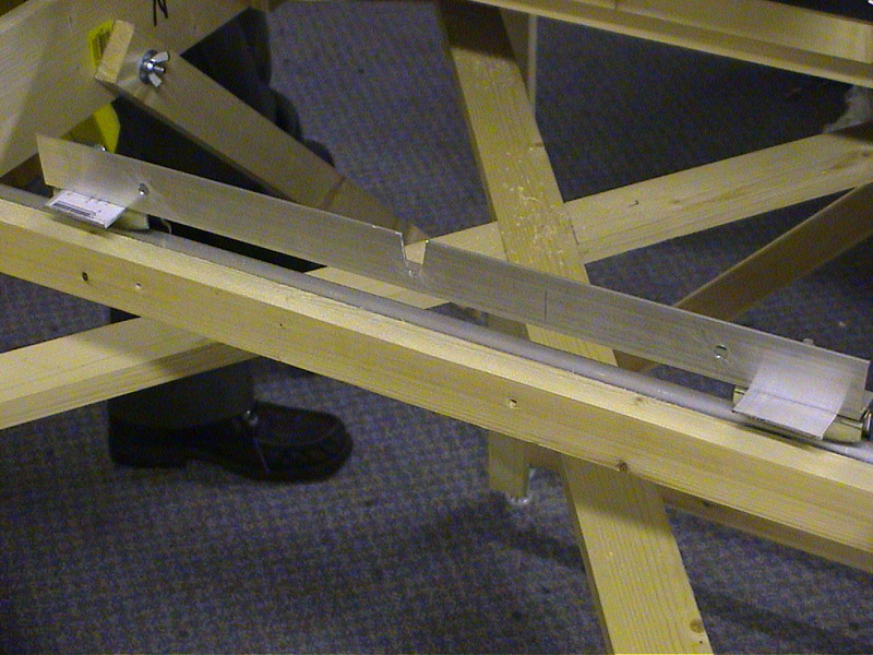
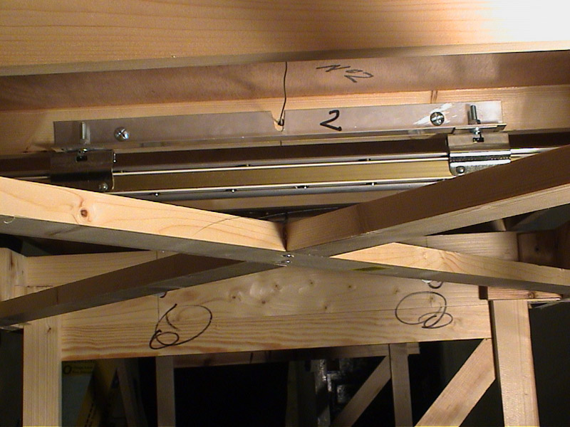
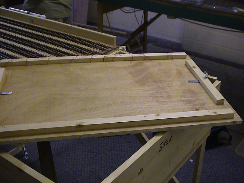
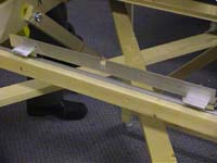
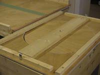
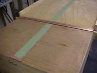
The sliding top can now be put in place and bolted to the slide arms. The views below taken underneath the traverser show the top fixed in place, with the bolt wires in situ.
|
|
|

|
|
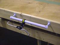
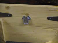
A handle is made from a DIY towel rail and bolted in place on the side of the traverser tray. The brake handle is attached to the handle as shown. The traverser should now slide easily backwards and forwards with the bolts locking into each set of holes on the locking plates. Some minor adjustments might be necessary to ensure this is the case.
|
 |
|
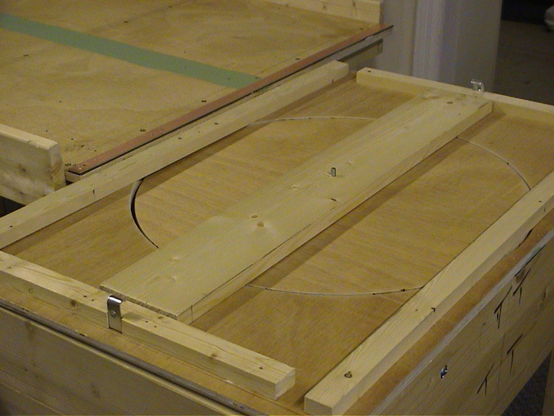
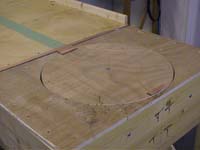
We now turn our attention to the tops of the two end pieces of the traverser (see weeks 2 & 3). A circular piece 18 inches diameter is removed from one top to form a turntable. |
|
This shows the underside of the turntable, with a central piece of timber to support the central bolt through turntable. Battons are fixed near the edges to locate into the main frame extensions. ( . |
 |
|
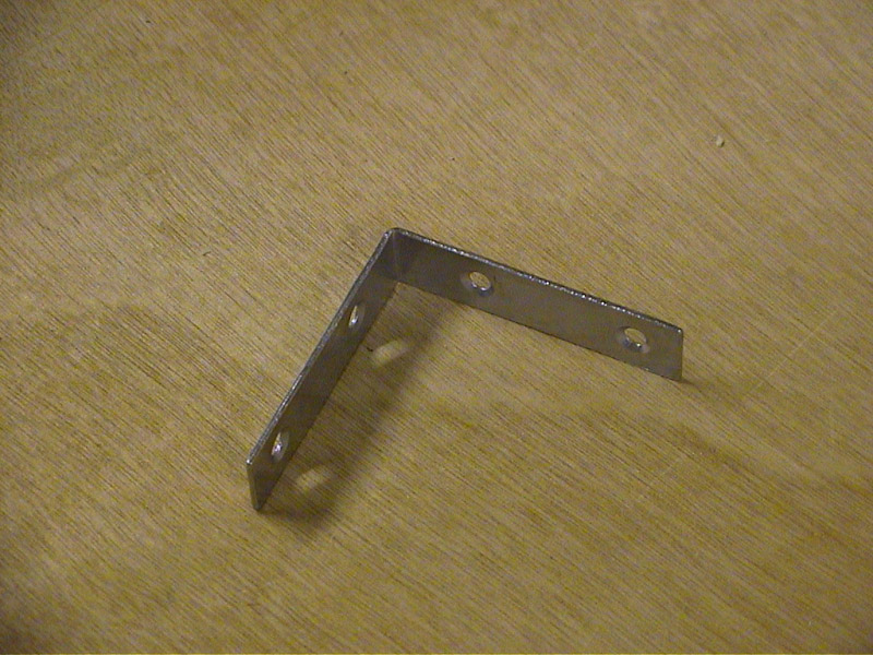
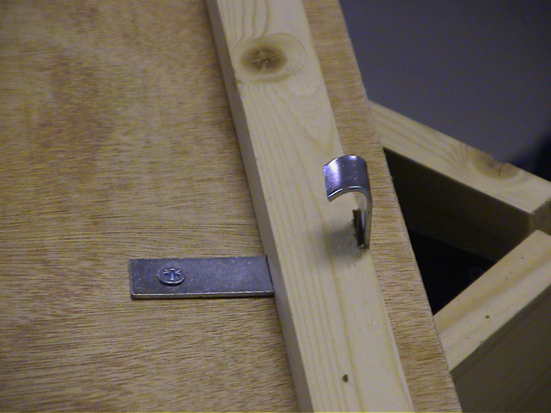
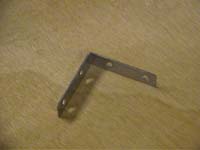
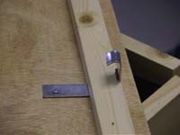
A clip is fashioned from a standard DIY 50mm angle bracket. The pictures below show a close up of the final clip and the corresponding bulldog clip on the main frame box.
|
|
 |
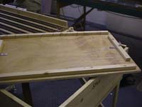
| The plain top at the other end is clipped in place in a similar fashion.
|
 |
|
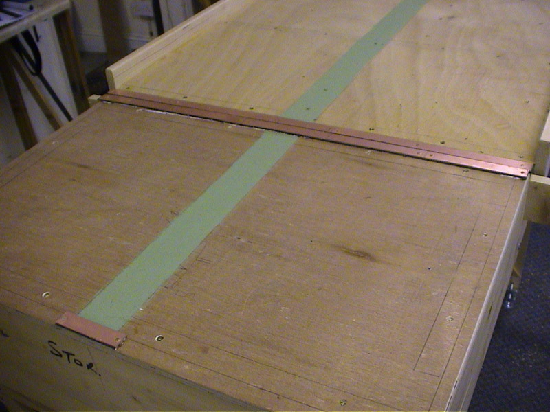
This final picture shows the underside of the plain top.
|
Next week we lay the track work.