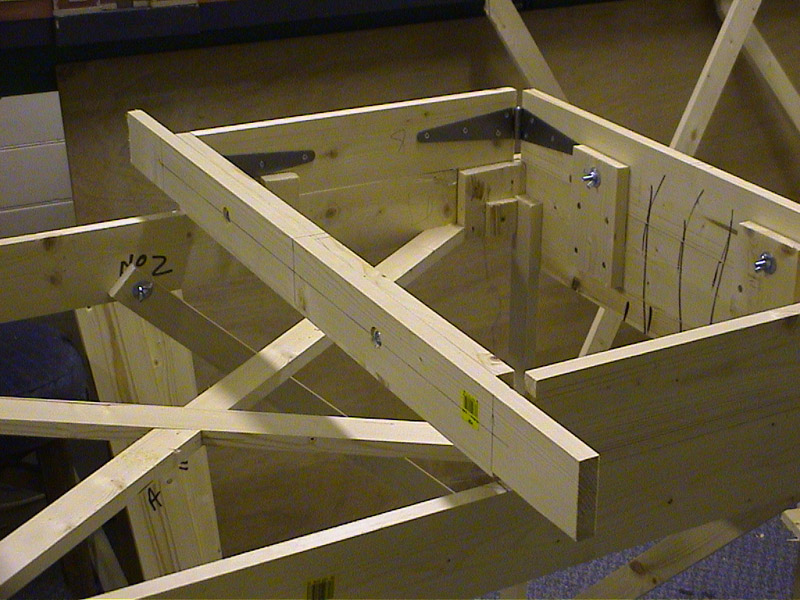
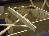
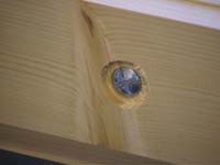
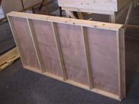
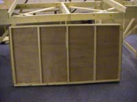
| An extra piece of 4in x 1in timber 3 foot 3 inches long is bolted to the centre face of each of the small boxes to act as the 'locking plate board'.
|
 |
|
The holes for the bolts are well countersunk, since the steel locking plate will be screwed to the outside face (next week).
|
|
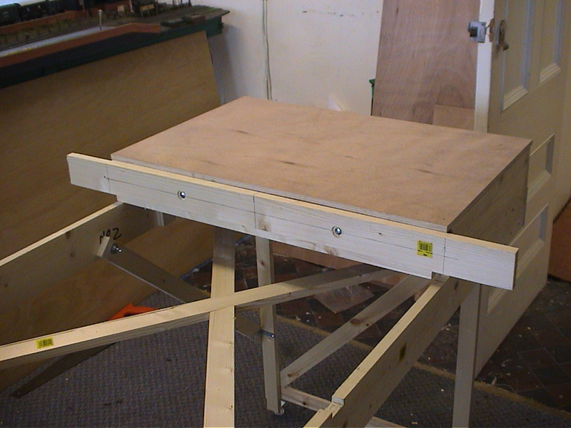
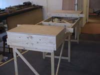
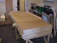
Rectangular pieces of 3/8th inch plywood is cut to fit the tops of each small box. These are laid in place at present and not fixed.
|
 |
|
 |
|
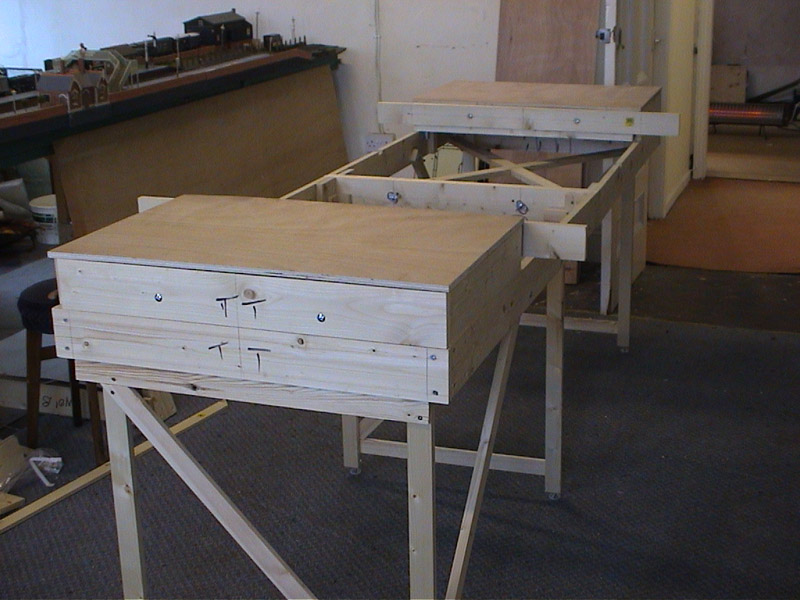
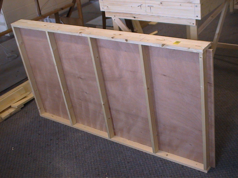
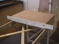
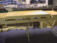
We now make the sliding tray for the centre. This is made of a piece of 3/8th inch plywood, 2foot 6 inches by 5 foot.
|
 |

|
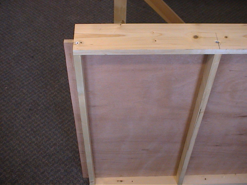
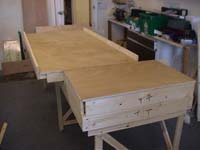
The two long sides are edged with 4in x 1in timber 57 inches long, such that one and a half inches of ply protrudes at each end.
The underside is strengthened by five pieces of 2in x 1in timber. |
 |
 |
|
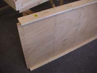
The picture to the left shows the top side of the sliding tray. The protrusion of the plywood is clear.
|
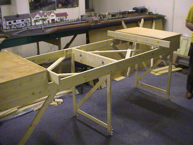
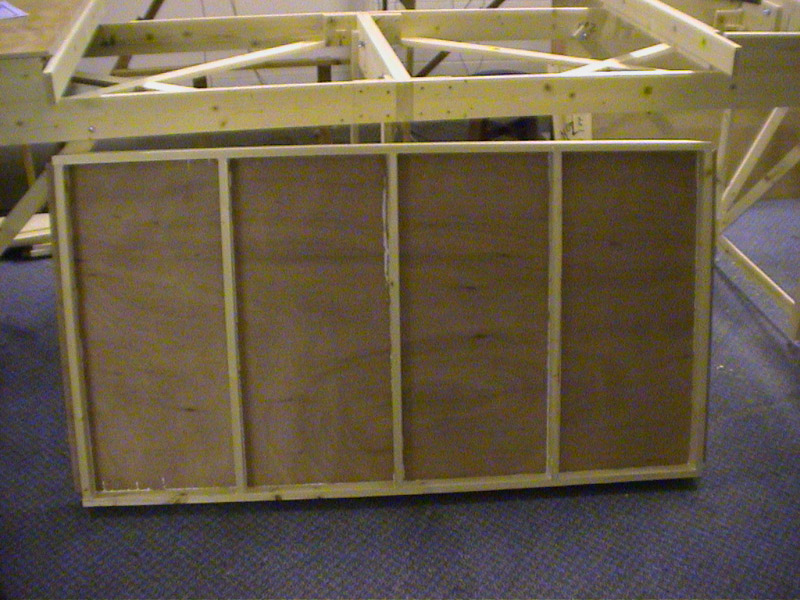
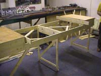
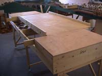
| The sliding tray is placed in the centre space of the unit. The pictures below show the tray moved slightly to one side for clarity.
|
 |
|
 |