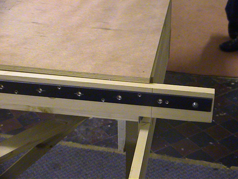
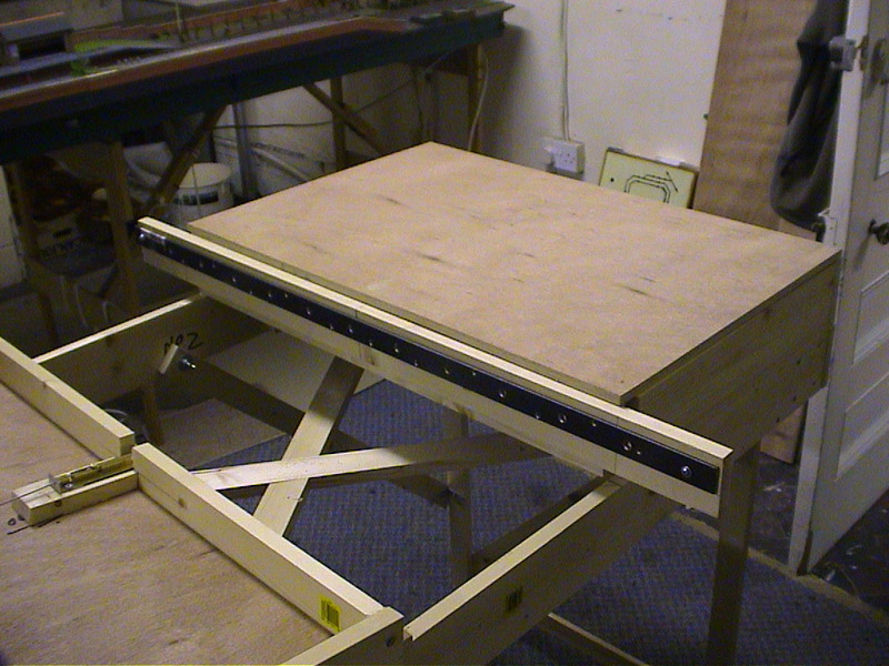
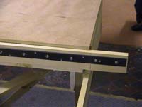
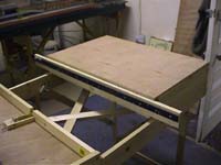
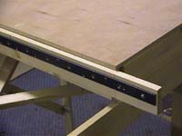
| Two locking plates are made steel strip with 1/4 inch holes drilled every 80 mm (3 3/16 inches). The plates are screwed to the boards at each end of the main structure (see the start of last week).
|
 |
|
 |
|
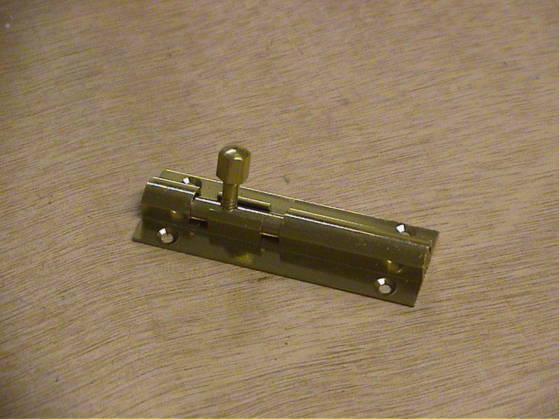
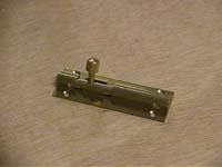
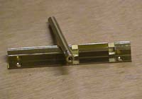
Two standard DIY 3 inch brass bolts are required
|
|
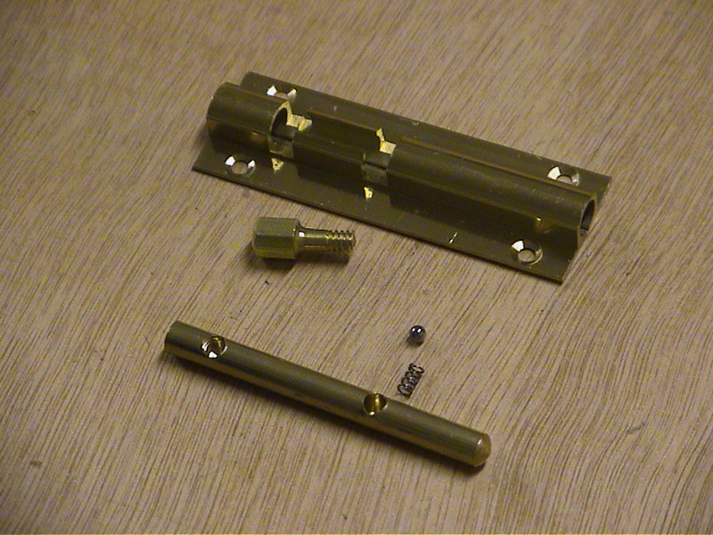
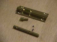
These are dismantled as shown. The end of the bolt is drilled through to the bolt-handle.
|
 |
|
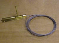
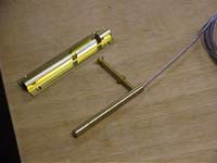
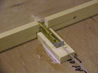
A length of standard bicycle steel wire brake cable is secured in the end of the sliding bolt with a standard N0 4 bolt. This will be cut down to size later. The sliding bolt is replaced into the bolt housing, without the roller ball mechanism.
|
|
 |
|
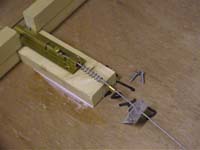
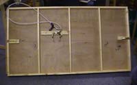
The sliding tray completed last week is turned upside down to allow the connectors to be fitted. A small notch is cut out in the centre of both the end cross pieces. The modified bolts from above are fitted in these notches, supported on a small block of wood.
|
 |
|
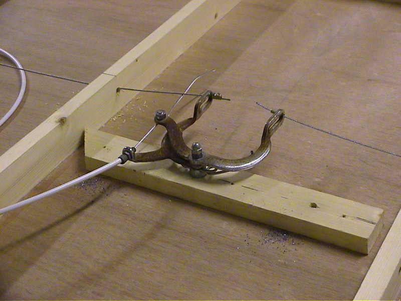
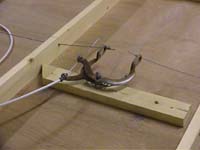
As can be seen in the picture above, a small spring is threaded on the bicycle brake wire and is held in place by a small piece of angle aluminium. The fixing screws for the bolt are screwed through the aluminium, holding it securely in place. A flat piece of aluminium at the other end of the bolt ensures that it remains level. |
|
The calliper arms of a standard bicycle brake (minus the brake shoes) is attached with a bolt to a block of wood fixed to the centre of the underside of the sliding tray. The arms where the brake shoes are normally attached is drilled through to take the brake cable. |
 |
|
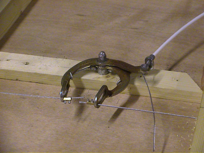
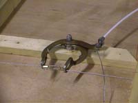
The cables from the bolts on either side are attached using a brass centre from a standard electrical connector block to secure.
|
| In this view the brake calliper has been closed, which pulls back the bolts from either side of the sliding tray.
|
 |
|
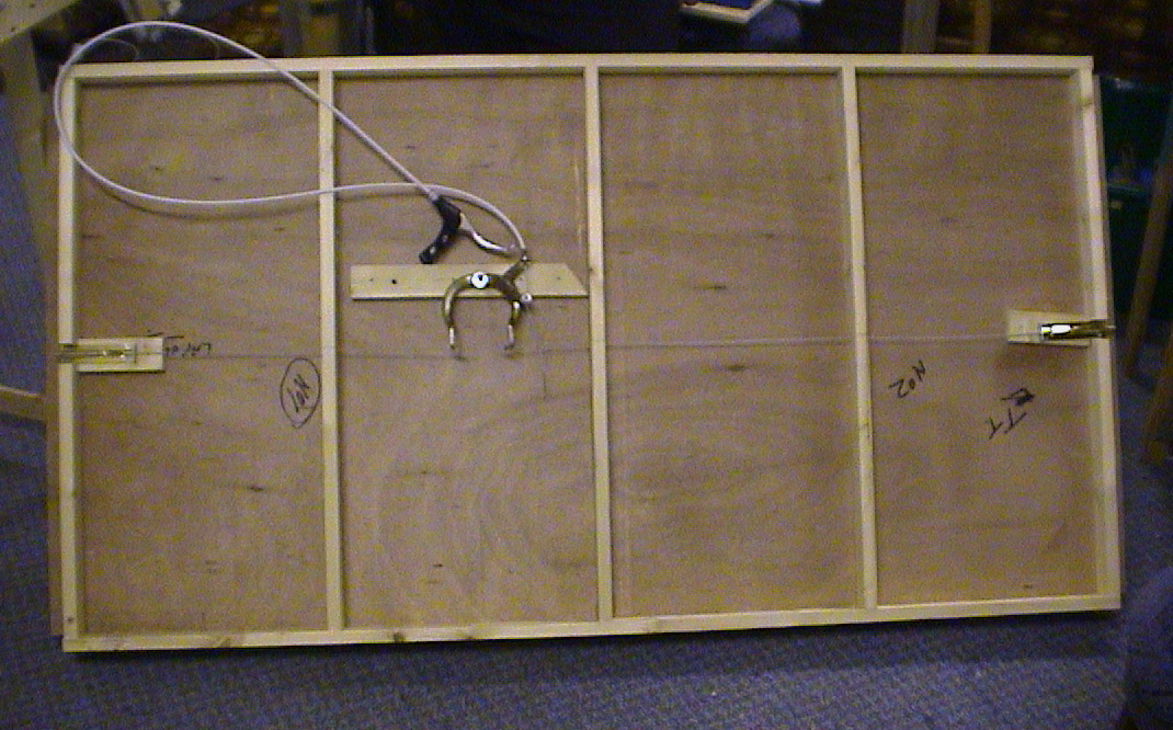
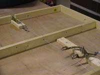
This final picture shows the complete underneath of the sliding board with both bolts connected to the brake calliper.
|
Next week we add the roller mechanism and finish making the traverser slide.